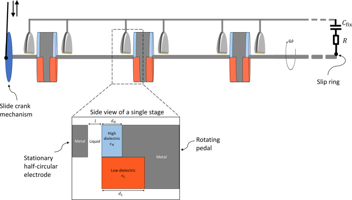
Fig. 2. Illustration of the energy harvesting device.
The device comprises of a multi-stage rotor structure, connected to a reservoir capacitor and to an electric load . The design of the rotor structure is presented (not to scale) with an additional side view of a single stage which consists of a rotating disc and a stationary half-circular metal electrode; in the gap between the two is a lubricating liquid. Each rotating disc is shared by two adjacent stages, connected in a back-to-back fashion, in order to save space, reduce the overall mass and prevent electric shortcuts. All the stages are mounted on a common metal axle, thereby effectively connecting all stages in parallel. To ensure the prevention of shortcuts between the metal axle and the bottom of the half-circular electrode, the bottom should be insulated, as depicted by a thin yellow line. The rotor can be spun by different means, in the figure we show one option of a slide-crank mechanism, however it can equally be rotated by a wind- or water-turbine. Mechanical components to optimize the shaft rotational velocity (gearset, freewheel, and flywheel) have been omitted from the illustration for clarity.

