Abstract
A method for isolating single crystalline sub-5 nm carbon coated iron nanoparticles (Fe@C NPs) from a carbon nanotube matrix has been developed. The isolation of such particles allows for their characterization by high resolution electron microscopy methods and SQUID magnetometry. While the NPs are superparamagnetic at room temperature, at 10 K they exhibit a coercivity nearly 30 times greater than that of commercial Fe3O4 NPs of comparable size. A novel nanotemplate directed assembly method for manipulating the particles at the individual particle level is also reported.
Magnetic particles comprise an important class of materials that have been used in data storage,1,2 water purification,3 magnetic resonance imaging (MRI),4-7 medical diagnostics, and therapeutics.7-9 A major challenge is learning how to synthesize nanoparticles (NPs) that have desirable magnetic properties, acceptable chemical stability, and surface chemistry that allow for deliberate and straightforward functionalization with surface active moieties.2,10,11 Among the materials explored in nanoscale forms thus far, Fe and FeOx are particularly attractive because they can be made from readily available, low cost precursors, exhibit rich compositional and structural diversity, and often have useful magnetic properties such as high saturation magnetization.5,12,13 However, NPs made primarily of Fe(0) typically are not stable because of their susceptibility to oxidation. Indeed, it is difficult to prepare and isolate sub-5 nm, predominantly Fe(0), NPs with a narrow size distribution and intact superparamagnetic properties. Here, we report a method for the preparation and isolation of single crystalline sub-5 nm Fe NPs, which are encapsulated with carbon (Fe@C NPs). The Fe@C NPs are superparamagnetic at room temperature, but at 10 K, they exhibit a coercivity nearly 30 times greater than that of commercial Fe3O4 NPs of comparable size. The improved magnetic properties, chemical stability, and surface functionality arising from the carbon coating are promising for many applications where iron oxide NPs are currently used, such as ferrofluids, medical diagnostics, and therapeutics.5,7,9,13,14
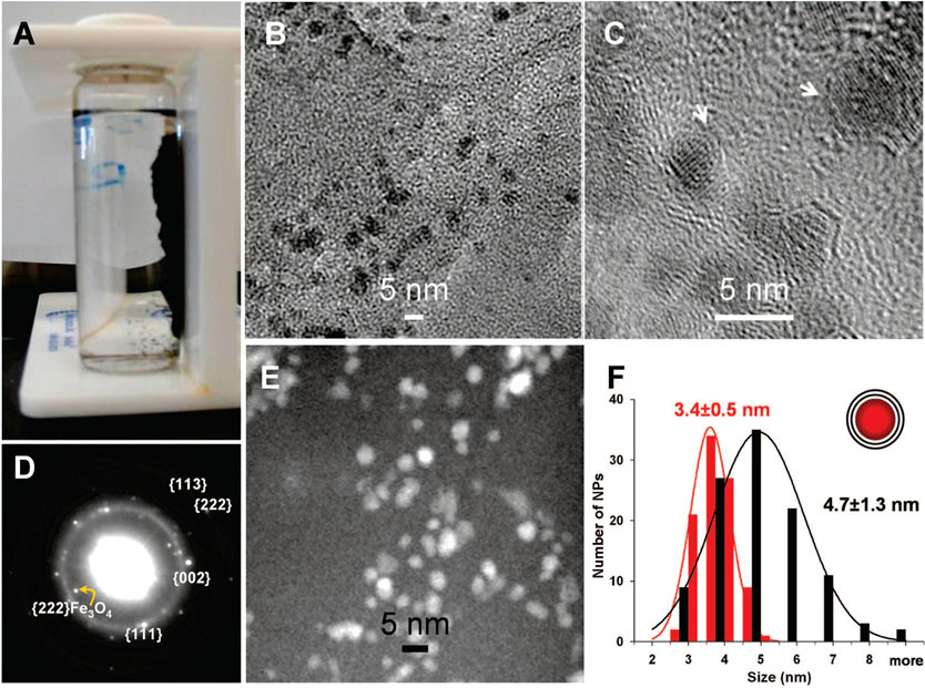
Prior work has shown that sub-5 nm Fe@C NPs are produced as a significant byproduct (20–40 wt %) in the synthesis of single-walled carbon nanotubes (SWNTs) via the high-pressure CO (HiPco) process;15,16 however, these particles have not been isolated and their structures have not been well characterized. In the HiPco reaction, Fe(CO)5 and CO (30–50 atm) are introduced in a flow reactor via separate channels at 1100–1200 °C, which results in the formation of iron clusters interspersed with carbon nanotubes. It is worth noting that others have shown that Fe@C NPs can be continuously produced in the HiPco process on a gram/h scale.15 We have discovered that these particles can be isolated from the raw HiPco materials by repeated centrifugation and the appropriate applied magnetic field (see Supporting Information). The particles also can be functionalized with dodecyl groups via reductive alkylation chemistry17 to improve their dispersibility in 1,2-dichlorobenzene (ODCB, 99%, Aldrich). The isolated NP product is magnetic with nearly all of the sample attracted to the side walls of a glass vessel in the presence of a bar magnet (Figure 1A). The yield of the magnetic NPs was about 15 wt % of the starting HiPco material, which contains 35 wt % iron according to thermogravimetric analysis (TGA).18
Figure 1.
Fe@C NPs. (A) Photograph showing suspended NPs (in ODCB) attracted to the wall of a glass vessel by a bar magnet. (B,C) Bright field TEM images of purified Fe@C NPs on a 3 nm thick carbon grid (B: low magnification; C: high magnification). (D) Electron diffraction pattern from ensemble of Fe@C NPs. The two dominant rings can be indexed by using a FCC-Fe lattice (a = 3.56 Å, d(111) = 2.05 Å, d(002) = 1.78 Å, d(113) = 1.07 Å, and d(222) = 1.03 Å). A small amount of Fe–Ox compounds, such as Fe3O4 (d(222) = 2.42 Å), are present as well. (E) STEM HAADF image. (F) Size distributions of the iron cores, determined from STEM, and the carbon shells, determined from bright field TEM. The size distributions follow Gaussian statistics. The diameter difference determined via the two modes corresponds to approximately two layers of carbon on the particles.
Transmission electron microscopy (TEM) analysis of the sample shows that the particles are crystalline with an average diameter of ~4.7 ± 1.3 nm (modeled as spheres), nearly identical to the average size of the particles observed in the raw HiPco material (Figure 1B,C and Figure S1, Supporting Information). This observation suggests that the process of isolation does not significantly change their size. The majority of these NPs are iron coated with carbon. For a small population of particles approximately 10 nm in diameter, the iron-core carbon–shell chemical structure could be resolved and characterized with high resolution TEM in conjunction with electron energy loss spectroscopy (EELS) (see Supporting Information, Figure S1). Proving the existence of carbon shells for the 3–6 nm particles is difficult due to their small size. Indeed, the shells are barely resolvable in the TEM images (Figure 1C) but can be independently confirmed by an indirect method based on the different resolution power of the bright field TEM (JEOL-2100F, operated at 200 kV) and Z-contrast scanning transmission electron microscopy (STEM) using a high-angle annular dark field detector (Gatan). While C and Fe are observed in bright field TEM of these particles (Figure 1B,C), only the heavy element, Fe, exhibits observable contrast in STEM mode (Figure 1E). The Fe cores can then be distinguished from the carbon shells by comparing the diffraction contrast TEM image to the Z-contrast STEM image. Using this method, we have constructed histograms of Fe particle sizes with and without their carbon shells (Figure 1F). This analysis shows that the carbon shell is on average approximately 0.7 nm thick, corresponding to two graphitic layers. Electron diffraction from the NPs shows a pattern consistent with a dominant FCC-Fe lattice, with a small component of Fe3O4 structure (Figure 1D).
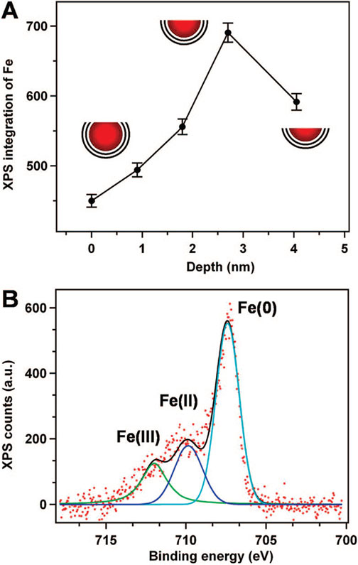
The iron-core carbon–shell structure was further confirmed by X-ray photoelectron spectroscopy (XPS) analysis. The XPS depth profile of the Fe@C NP films shows that as the outermost layer of C (shell) is removed by Ar+ sputtering, increasing amounts of Fe (core) are exposed, resulting in an increase in the Fe signal (Figure 2A). Subsequent Ar+ sputtering removes more Fe from the core, eventually causing a decrease in the Fe signal. This “peaking” behavior in the depth profile is consistent with the Fe@C structure deduced from the TEM analysis. The elemental analysis by XPS reveals that greater than 60% of the iron core is in the Fe(0) form (Figure 2B and Figure S3 in the Supporting Information). Collectively, such observations confirm that these NPs are different from the carbon-encapsulated iron oxide and iron carbide NPs reported previously.19
Figure 2.
X-ray photoelectron spectroscopy (XPS) analysis. (A) Iron signal as a function of sputtering time. The sputtering rate was ~0.9 Å/min. (B) XPS of a thin film of NPs on a gold substrate showing Fe(0):Fe(II):Fe(III) ~ 3.4:1.3:1, as inferred from modeling the spectrum with three appropriate oscillators.
The analysis above confirms speculation that the majority of the NPs formed in the HiPco process have a Fe@C structure.15,16,18,20,21 This is further substantiated by the fact that these structures are not degraded by 1–6 M HCl due to the protective carbon layer.18,20,21 The carbon coating is likely the catalyst poison in the HiPco process, where iron catalyzes the disproportionation of CO at high pressure and temperature to nucleate and grow single-walled carbon nanotubes.
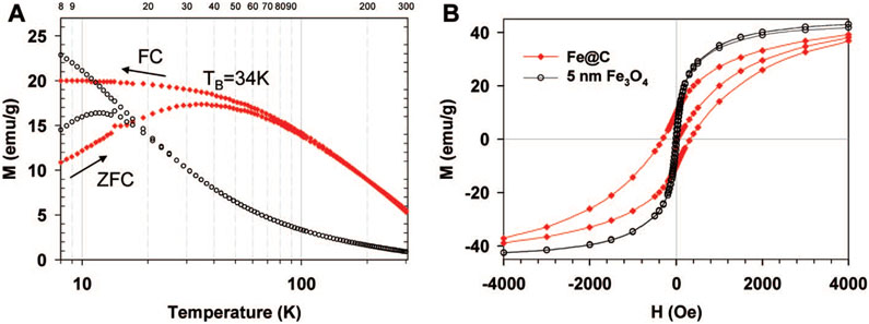
The magnetic properties of the sub-5 nm Fe@C NPs are equally interesting. They exhibit a blocking temperature (TB) of 35 K, which is ~3 times greater than that of commercial Fe3O4 NPs with a slightly larger size (5.0 ± 0.8 nm, Ocean NanoTech, Fayetteville, AR) (Figure 3A). The increased blocking temperature indicates the Fe@C NPs are less susceptible to flipping of the magnetization vector due to thermal fluctuations.22 Interestingly, the Fe@C NPs also exhibit a coercivity (Hc) nearly 30 times greater than that of slightly larger commercial Fe3O4 NPs (313 Oe vs 11.3 Oe, Figure 3B) and more than twice that of 9.58 ± 2.53 nm magnetite Fe3O4 particles (150 Oe) prepared by sol–gel methods.23
Figure 3.
Fe@C NPs show enhanced magnetic properties in comparison to Fe3O4 NPs of comparable size. (A) Zero field cooling and field cooling curves for Fe@C NPs (red diamond) compared to 5 nm Fe3O4 NPs (black circles). The applied field was 500 Oe. (B) Magnetic field dependence of magnetization at 10 K. The magnetization of Fe3O4 is scaled 40× in (A) and 5× in (B). The measurements were carried out using a superconducting quantum interference device (SQUID) magnetometer (see Supporting Information).
The enhanced magnetic properties of the Fe@C NPs are presumably due to the protective nature of the carbon coatings. Interestingly, iron-free carbon nanotube/NP samples are diamagnetic (see Supporting Information, Figure S4) and do not exhibit superparamagnetism like the Fe@C NPs. Therefore, we suggest that the carbon coating of the Fe@C NPs not only prevents the iron core from oxidation but also improves the magnetic stability of the Fe core by reducing the magnetic interactions (e.g., magnetic coupling) among the densely packed single domain particles.1,19 Moreover, the carbon coating provides these Fe@C NPs with stability in a variety of organic and inorganic media19 and may allow one to chemically tailor their surfaces for applications requiring biocompatibility.
To fully utilize such sub-5 nm superparamagnetic Fe@C NPs, one needs methods for manipulating them at the single particle level. Interestingly, we have discovered that 16-mercaptohexadecanoic acid (MHA)-templates prepared by dip-pen nanolithography (DPN)24-26 can be used to assemble them into single-NP per feature nanoarrays (Figure 4). In a typical experiment, DPN was used to generate dot arrays of MHA on a gold surface. The dot diameter was varied from 50 to 120 nm with a fixed spacing of 400 nm, and the exposed gold was passivated with 1-octadecanethiol (ODT). Particle assembly was then studied as a function of dot size.
Figure 4.
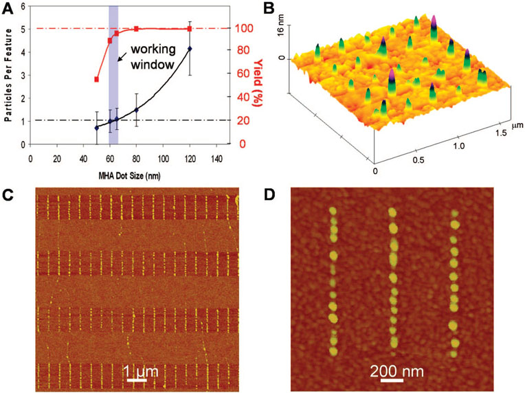
Directed assembly of Fe@C NPs with single particle control. (A) Number of particles per site as a function of the size of MHA dot patterns. Highlighted in blue is the ideal working window for assembly with single particle resolution and high yield. (B) AFM topographic images showing individual Fe@C NPs assembled on 60 nm MHA dots in an array. (C) Individual Fe@C NPs line up along DPN-patterned 70 nm wide MHA lines. (D) Zoom-in image of a portion of “C” showing single particle control. Note that NPs look bigger due to tip convolution.
To effect particle assembly, a drop of ODCB containing Fe@C NPs (~50–200 mg/L) was rolled over the patterned substrates. Because ODCB wets the MHA features but not the ODT passivated regions, NPs are guided to and localized on the hydrophilic regions of the substrate. We have used this method in related work to assemble carbon nanotubes as well.27,28 Remarkably, by using it we can generate NP arrays, where each feature holds a single NP. By studying this process as a function of MHA feature size, we have determined the optimum feature size for single particle control to be 60 nm. Below this size, one observes a low yield of particles on MHA features, while above it, multiple particles often occupy each feature (Figure 4A, and Figure S5, Supporting Information). A representative nanoarray of individual Fe@C NPs assembled on 60 nm MHA dot features shows that the process is quite efficient, with greater than 90% of the features each holding a single NP (Figure 4B). Finally, one can systematically control the placement and configuration of particles simply by controlling the template. For example, 70 nm wide MHA line features, spaced 1 μm apart, yield well-defined rows of NPs on each of the MHA lines (Figure 4C,D). Such capabilities point toward the potential for studying NP properties such as superparamagnetism at the single particle level.
Supplementary Material
Acknowledgment.
We thank Carbon Nanotechnology Laboratory at Rice University for the HiPco material and Dr. Jae-Won Jang and Dr. Sergei Rozhok for helpful discussions. C.A.M. acknowledges DARPA, NSF-NSEC, and CCNE for support of this work, and V.P.D. acknowledges NSF-MWN and NSF-NSEC support. C.A.M. is also grateful for a NSSEF Fellowship. D.M. acknowledges the Ministerio de Ciencia y Tecnología for a RyC contract. The TEM work was performed in the EPIC facility of the NUANCE Center at Northwestern University, which is supported by NSF-NSEC, NSF-MRSEC, Keck Foundation, the State of Illinois, and Northwestern University.
Footnotes
Supporting Information Available: Detailed experimental procedures, EDX, additional SQUID, XPS, AFM, and TEM data. This material is available free of charge via the Internet at http://pubs.acs.org.
References
- (1).Hayashi T; Hirono S; Tomita M; Umemura S Nature 1996, 381, 772–774. [Google Scholar]
- (2).Marinero EE Materials Challenges for Tb/In2 Magentic Recording. In Springer Series in Materials Science: Springer: Berlin, Heidelberg, 2007; Vol. 94 (Magnetic Nanostructures), pp3–6. [Google Scholar]
- (3).Yavuz CT; Mayo JT; Yu WW; Prakash A; Falkner JC; Yean S; Cong L; Shipley HJ; Kan A; Tomson M; Natelson D; Colvin VL Science 2006, 314, 964–967. [DOI] [PubMed] [Google Scholar]
- (4).Bulte JWM; Kraitchman DL NMR Biomed. 2004, 17, 484–499. [DOI] [PubMed] [Google Scholar]
- (5).Corot C; Port M; Guilbert I; Robert P; Raynal I; Robic C; Raynaud J-S; Prigent P; Dencausse A; Idee J-M Superparamagnetic Contrast Agents; CRC Press LLC: Boca Raton, FL, 2007; pp 59–83. [Google Scholar]
- (6).Seo WS; Lee JH; Sun X; Suzuki Y; Mann D; Liu Z; Terashima M; Yang PC; McConnell MV; Nishimura DG; Dai H Nat. Mater 2006, 5, 971–976. [DOI] [PubMed] [Google Scholar]
- (7).Pankhurst QA; Connolly J; Jones SK; Dobson J J. Phys. D 2003, 36, R167–R181. [Google Scholar]
- (8).Reiss G; Huetten A Nat. Mater 2005, 4, 725–726. [DOI] [PubMed] [Google Scholar]
- (9).Douziech-Eryrolles L; Marchais H; Herve K; Munnier E; Souce M; Linassier C; Dubois P; Chourpa I Int. J. Nanomed 2007, 2, 541–550. [PMC free article] [PubMed] [Google Scholar]
- (10).Dravid VP; Host JJ; Teng MH; Elliott B; Hwang J; Johnson DL; Mason TO; Weertman JR Nature 1995, 374, 602. [Google Scholar]
- (11).Tartaj P; Morales MDP; Veintemillas-Verdaguer S; Gonzalez-Carreno T; Serna CJ J. Phys. D 2003, 36, R182–R197. [Google Scholar]
- (12).Hyeon T Chem. Commun 2003, 927–934. [DOI] [PubMed] [Google Scholar]
- (13).Cheng F-Y; Su C-H; Yang Y-S; Yeh C-S; Tsai C-Y; Wu C-L; Wu M-T; Shieh D-B Biomaterials 2004, 26, 729–738. [DOI] [PubMed] [Google Scholar]
- (14).Raj K; Moskowitz RJ Magn. Magn. Mater 1990, 85, 233–245. [Google Scholar]
- (15).Bronikowski MJ; Willis PA; Colbert DT; Smith KA; Smalley RE J. Vac. Sci. Technol., A 2001, 19, 1800–1805. [Google Scholar]
- (16).Nikolaev P; Bronikowski MJ; Bradley RK; Rohmund F; Colbert DT; Smith KA; Smalley RE Chem. Phys. Lett 1999, 313, 91–97. [Google Scholar]
- (17).Liang F; Sadana AK; Peera A; Chattopadhyay J; Gu Z; Hauge RH; Billups WE Nano Lett. 2004, 4, 1257–1260. [Google Scholar]
- (18).Wang Y; Shan H; Hauge RH; Pasquali M; Smalley RE J. Phys. Chem. B 2007, 111, 1249–1252. [DOI] [PubMed] [Google Scholar]
- (19).Wang CF; Wang JN; Sheng ZM J. Phys. Chem. C 2007, 111, 6303–6307. [Google Scholar]
- (20).Xu Y-Q; Peng H; Hauge RH; Smalley RE Nano Lett. 2005, 5, 163–168. [DOI] [PubMed] [Google Scholar]
- (21).Chiang IW; Brinson BE; Huang AY; Willis PA; Bronikowski MJ; Margrave JL; Smalley RE; Hauge RH J. Phys. Chem. B 2001, 105, 8297–8301. [Google Scholar]
- (22).Zhang YD; Budnick JI; Hines WA; Chien CL; Xiao JQ Appl. Phys. Lett 1998, 72, 2053–2055. [Google Scholar]
- (23).Liu X; Fu L; Hong S; Dravid VP; Mirkin CA Adv. Mater 2002, 14, 231–234. [Google Scholar]
- (24).Piner RD; Zhu J; Xu F; Hong S; Mirkin CA Science 1999, 283, 661–663. [DOI] [PubMed] [Google Scholar]
- (25).Lim JH; Ginger DS; Lee KB; Heo J; Nam JM; Mirkin CA Angew. Chem., Int. Ed 2003, 42, 2309–2312. [DOI] [PubMed] [Google Scholar]
- (26).Ginger DS; Zhang H; Mirkin CA Angew. Chem., Int. Ed 2004, 43, 30–45. [DOI] [PubMed] [Google Scholar]
- (27).Wang Y; Maspoch D; Zou S; Schatz GC; Smalley RE; Mirkin CA Proc. Natl. Acad. Sci. U.S.A 2006, 103, 2026–2031. [DOI] [PMC free article] [PubMed] [Google Scholar]
- (28).Zou S; Maspoch D; Wang Y; Mirkin CA; Schatz GC Nano Lett. 2007, 7, 276–280. [DOI] [PubMed] [Google Scholar]
Associated Data
This section collects any data citations, data availability statements, or supplementary materials included in this article.


