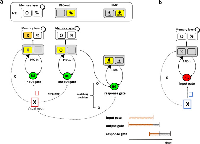
Fig 1. Schematic of the PBWM architecture for canonical gating operations.
(a) The gating system is composed of three core circuits that are hierarchically arranged from left to right. For illustration the operations needed to solve the task used in this paper are shown. At the beginning of a trial, the memory layer actively maintains the information from the previous trial (e.g., “O” and “%”). Sensory information (e.g., the “X” in the visual input) is transiently represented in a prefrontal cortex layer (labeled “PFC-in”). The input gate controls whether the new visual information (e.g., “X”) is updated to be maintained in a PFC memory layer, and if so, to which address or anatomical “stripe” within that layer (selective gating). The colored frame in the visual input represents a task cue signifying the updating policy that should be taken by the input gate. In this example, the red frame indicates that memory should be updated, so the input gate selectively updates the right PFC stripe (corresponding with the letter category, replacing the “O” in memory with “X”). The output gate controls which memory representations is prioritized in PFC-out (e.g., a deep layer of the PFC) to influence subsequent processing (e.g., here the relevant representation in memory is “O” and not “%”, given that the input to be compared is in the letter category). The response gate controls which motor response to select (e.g., here “same” (S) or “different” (D)) in posterior prefrontal layer (labeled here PMC), by comparing the output-gated memory representation (“O”) with the current visual input (“X”). Gate switching at the output and response gates are reflected by the change in the active stripe between the previous trial (t-1) and in the current trial. (b) An example of a maintenance trial. The blue task cue indicates that the appropriate updating policy is maintenance, and thus sensory information (e.g., “X”) is prevented from being updated in PFC memory (the gating signal from the BG is therefore a No-Go, indicated by the red BG). Gate switching in the input gate corresponds with moving between updating state (as shown in a) and maintenance state (as shown in b). Yellow squares indicate active stripe selected by the corresponding gate. The orange square represents the newly updated stripe in memory. The predicted temporal order of the gating loops is depicted at the bottom right of the figure with input and output gating starting roughly at the same time continuing in parallel (indicated in orange) with output gating terminating later (serial termination indicated in grey). The response gate is expected to initiate with some delay due to conflict at upper levels, and to terminate even later than the output gate.

