
Fig. 2.
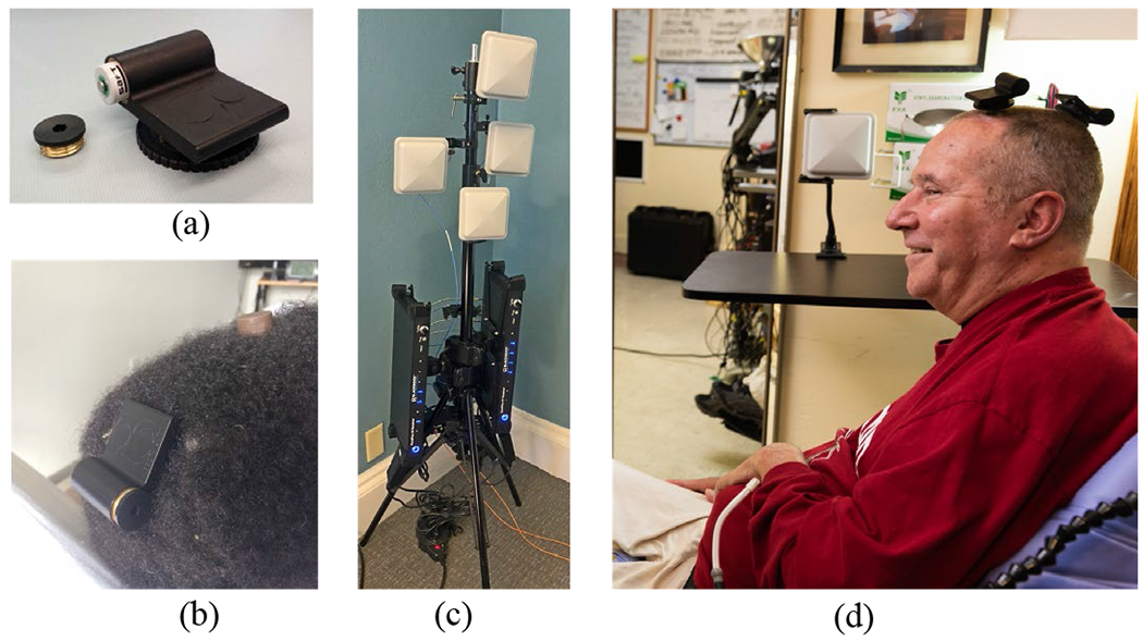
Some components of the wireless system, (a) BWD transmitter (52 mm x 44 mm) showing battery compartment. Turn-screw disc is used to attach the device onto a percutaneous pedestal, (b) The BWD connected to T10’s posterior pedestal (here, the anterior pedestal is covered by a protective cap), (c) A two-frequency wireless receiver system in a four-antenna configuration as deployed for T10. The output optical fibers (orange) connect to downstream NSPs. (d) T5 in his home with two transmitters. The antenna in the background was one of four mounted around the room. Photos used with permission.