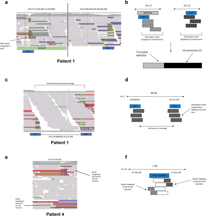
Figure 1.
IGV images and schematics of some of the identified insertions and structural variants. (A) Image of the translocation between Chromosomes 17 and 22 in Patient 1 that interrupts MAP2K4. Discordant reads on each chromosome map to the other end of the translocation. The split reads on Chromosome 17 map to a non-reference Alu element. The Alu element suspected to be involved in the translocation on Chromosome 17 (from the split reads) is shown as a blue box, and the reference Alu involved with the translocation on Chromosome 22 is also shown as a blue box. (B) A schematic showing the translocation event (not to scale). The Alu elements associated with the translocation are shown as blue boxes. The discordant reads are shown as gray or purple boxes. A schematic of the translocation is shown below the arrow. (C) Deletion involving Alu elements in Patient 1. Alu elements involved in the deletion are shown as blue boxes below the image. (D) A schematic of the deletion involving two Alu elements. Each Alu element is shown in blue, with the discordant reads shown in red. (E) Somatic Alu element insertion in Patient 4. The reads that map to the head and tail of the element are labeled by arrows. (F) A schematic of the Alu insertion on Chromosome 10. The approximate location of the insertion (blue box) is shown with the split and discordant reads mapping to the head of the Alu shown in white and red boxes, while the split and discordant reads mapping to the tail of the Alu are shown in white and green boxes.

