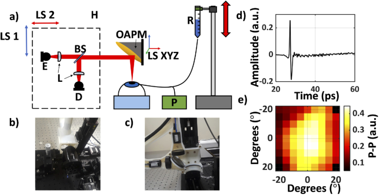
Fig. 2.
(a) A schematic of the setup used in the second (porcine) study. E, emitter; D, detector; BS, silicon beam splitter; R, saline reservoir; P, Pressure sensor; OAPM, off-axis parabolic mirror; H, 3D-printed housing unit containing the imaging optics, mounted on the LS1 and LS2, linear stage motors, used to move the housing; LS XYZ, a 3-axis linear motorized stage used for 3D positioning and adjustments of the OAPM; (b) An image of the entire system. (c) Photograph of the 3D-printed housing mounted on its accompanying linear stages (LS1 and LS2). (d) A representative THz-TDS signal from the center of the image. (e) An equiangular raster scan image of the corneal sample formed using the p-p of the reflected THz pulse.

