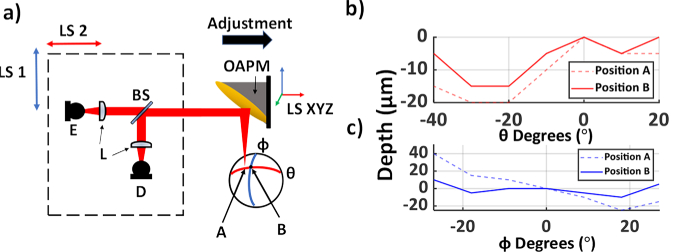
Fig. 3.
(a) A schematic of the setup. E, emitter; D, detector; BS, silicon beam splitter; LS 1 and 2, Linear stage motors designated to move the emitter and detector in tandem for beam steering; LS XYZ, 3D linear stage motors controlling the OAPM’s position. (b-c) Depth differences across the θ and φ axes at positions A and B, where position A is intentionally misaligned and B represents the properly aligned sample. The scanning range differs between the two axes due to the asymmetric nature of the OAPM’s FOV.

