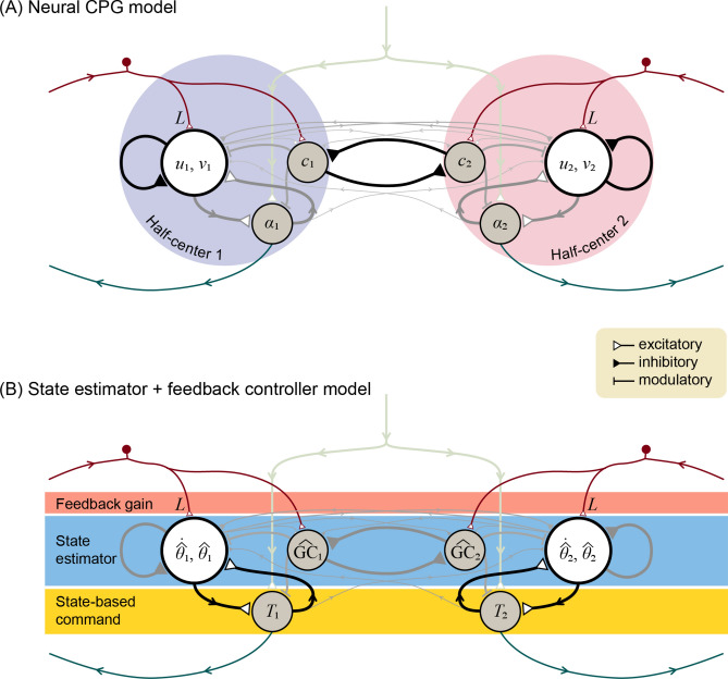
Figure 4.
Locomotion control circuit interpreted in two representations: (A) Neural central pattern generator with mutually inhibiting half-center oscillators, and as (B) state estimator with feedback control. Each half-center has a primary neuron with two states ( and , respectively), an auxiliary neuron for registering ground contact, and an alpha motoneuron driving leg torque commands. Inputs include a tonic descending drive, and afferent sensory data with gain . State estimator acts as second-order internal model of leg dynamics to estimate leg states (hat symbol denotes estimate) and ground contact , which drive state-based command . The estimator dynamics and estimator parameters including sensory feedback , and thus the corresponding neural connections and weights, are designed for minimum mean-square estimation error. Leg dynamics have nonlinear terms (see “Methods” section) of small magnitude (thin grayed lines).

