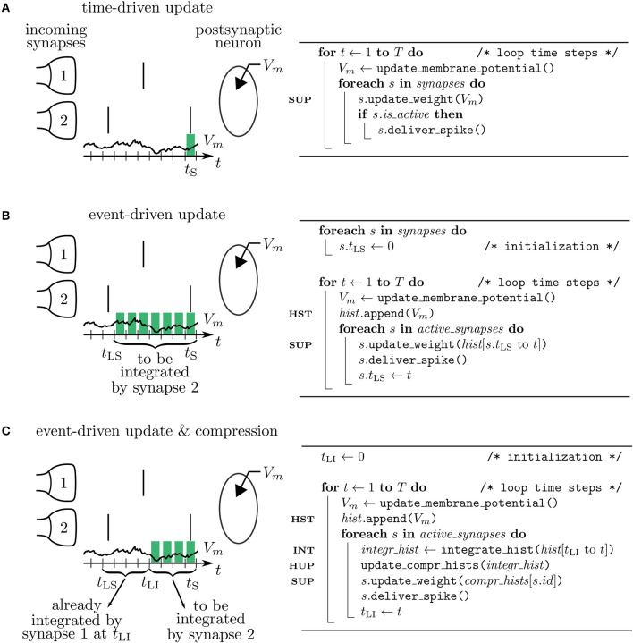
Figure 4.
Simulation concepts. Left: illustration of processing the postsynaptic voltage trace Vm (t) for three simulation concepts. Two incoming synapses (1 and 2) transmit spikes (black, vertical bars) to the postsynaptic neuron. Depending on the algorithm, a different number of past membrane potentials has to be stored (green blocks) so that synapse 2 can update its weight when it delivers the spike at time tS. Right: corresponding pseudocodes. (A) In the time-driven update scheme the synaptic weight change is evaluated in every time step of the simulation for all the synapses. This requires only the latest value of the membrane potential to be accessible by the synapse to update its weight at tS (see line marked SUP in pseudocode). (B) In the event-driven update scheme the computation of the synaptic weight change is performed only if a spike crosses the synapse. Therefore, storage of the time trace of Vm (see HST in code) from the last spike delivered by synapse 2 at tLS up to the current time step tS is needed. (C) In the compressed event-driven update scheme synapse 2 uses the time trace of Vm integrated from the last incoming spike at tLI up to the current time step tS (see INT in code) to complete its weight update (see SUP in code) and also to advance that of synapse 1. The preceding part of Vm from tLS to tLI was already integrated and applied to all incoming synapses (see HUP in code) by synapse 1 when it delivered the spike at tLI.

