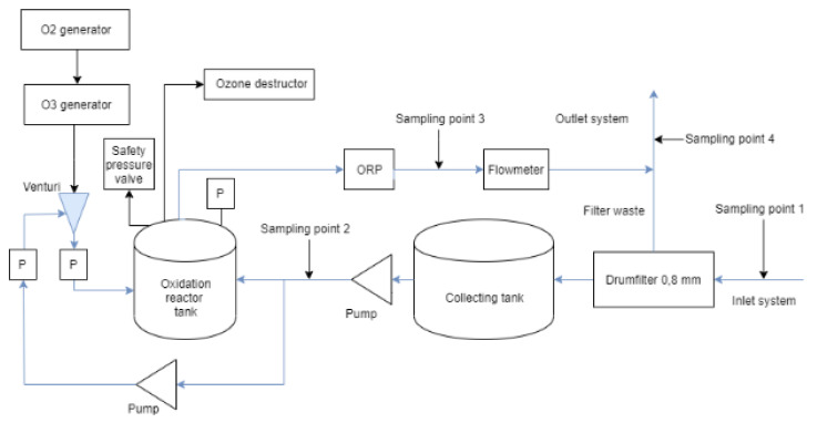
Figure 1.
Schematic picture of the pilot-scale system inside the container. The water inlet is from the right in the picture, then it passes through a drum filter before entering the collection tank. From the collection tank, the water goes to the oxidation reactor tank. The treated water is used to flush out filter waste from the drum filter from the container. It also shows the sampling points 1–4. “P” in the figure means pressure sensor and ORP is an in-line sampling point for oxidation-reduction potential.

