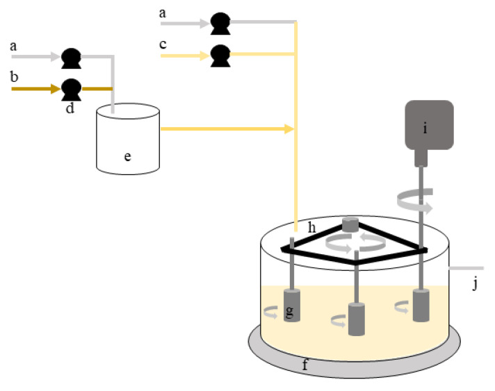
Figure 1.
Scheme representative of the rotating cylinder reactor: (a)—inlet of sterile air; (b)—inlet of concentrated nutrient medium; (c)—inlet of diluted nutrient medium; (d)—peristaltic pumps; (e)—chemostat; (f)—rotating cylinder reactor; (g)—testing cylinders (samplers); (h)—synchronising belt that connect the three cylinders; (i)—stirrer that controls rotation speed; (j)—outlet of bacterial suspension.

