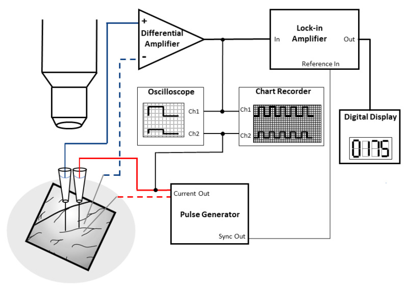
Figure 4.
Cartoon explaining the in vivo electrical resistance measurement method of brain surface microvessels. On the left side, a cranial window allows the exposure of surface vessels for the measurement. From the two electrode pairs, one is for current injection (red), while the other one is for the potential measurement (blue) with rectangular pulses. The glass microelectrodes are filled with KCl buffer. Recordings are helped by a lock-in amplifier and an oscilloscope. Electrode insertion is controlled by precision observation using a microscope. Modified from [3].

