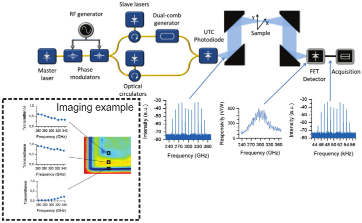
Figure 7.
Block diagram of the THz dual-comb imaging system. The first optical frequency comb is generated from the output of the master laser by two phase modulators, and then two teeth (with a frequency spacing equal to the central THz signal to be generated) are filtered by optical injection locking and a dual-comb signal is created from one of them; both signals are recombined on an uni-traveling-carrier (UTC) photodiode. The emitted THz signal is focused on the sample plane and detected later by a FET detector. The insets show (from left to right) the spectrum of the THz dual-comb, the responsivity of the FET detector and the spectrum of the multi-heterodyne signal after detection. The imaging example presents the transmittance spectra through the complex plastic sample at several locations, enabling a straightforward separation between plastic layers (differences in the overall absorbance and the frequency dependent slope) and the edge diffraction. Reproduced from Ref. [361].

