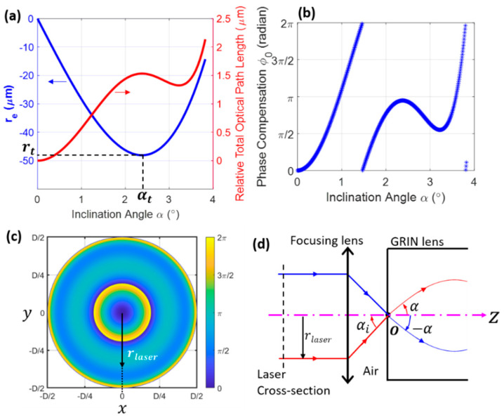
Figure 4.
Simulated phase compensation. and relative optical path difference (a) and phase compensation (b) as a function of α. (c) Simulated phase compensation along the laser beam cross-section (vertical dashed line in (d)), which is needed for obtaining the pattern shown in the bottom panel of Figure 2b. (d) Schematic showing the radial position of the incident laser beam, , corresponding to a ray with inclination angle . In (c), D is the laser beam diameter. Simulation parameters are identical to those in Figure 2.

