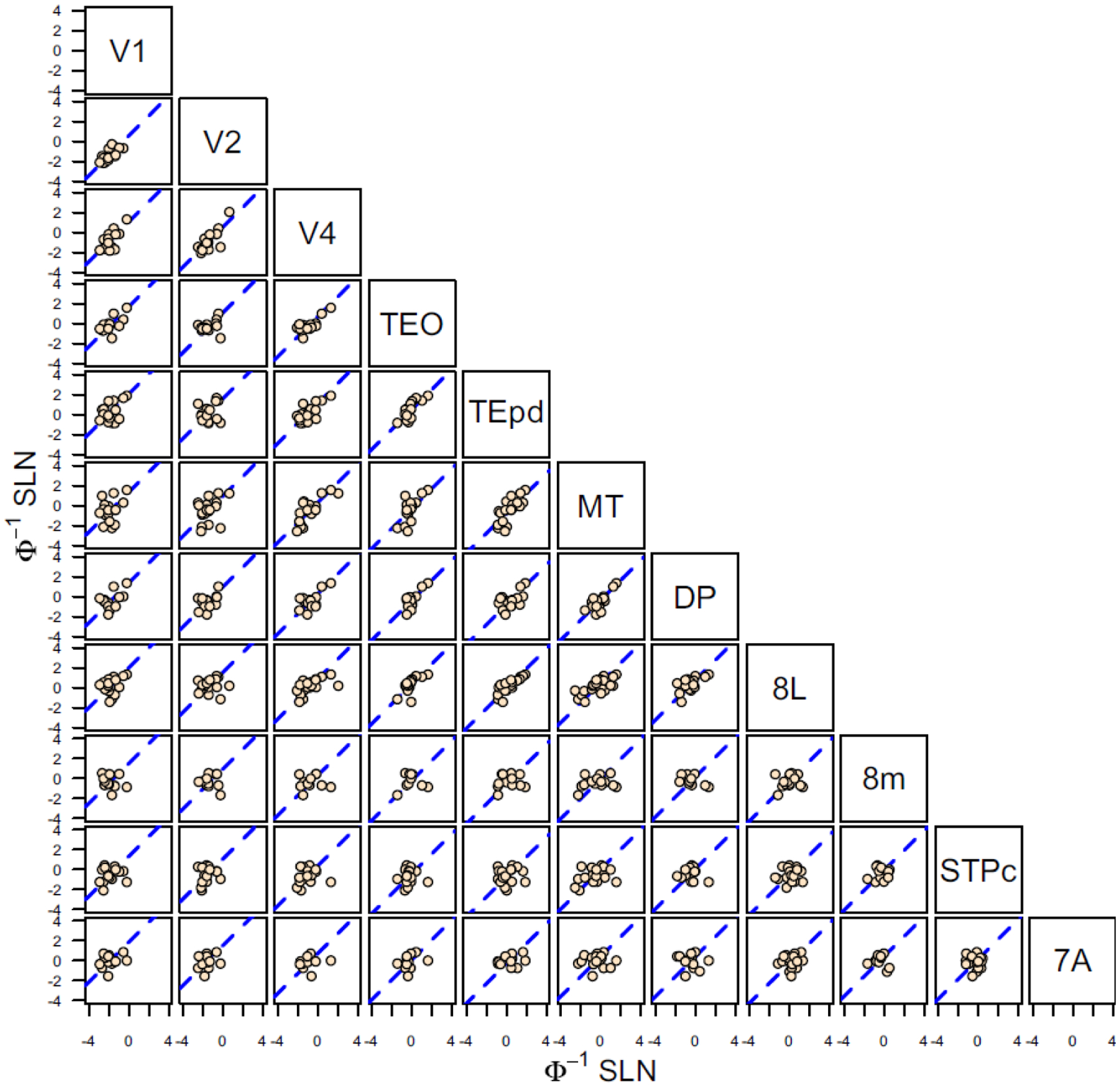
Figure 5. Probit transformation.

Scatter plots of probit transformed SLN values of common source areas from pairs of 11 visual areas, obtained from retrograde tracer injections. The absicssa of each graph corresponds to the transformed SLN values of area i, indicated on the diagonal at the top of the column and the ordinate values are the transformed SLN values of area j indicated on the diagonal at the right of the row. The dashed blue line in each plot is the best fit line of unit slope (replotted from (Markov et al., 2014b)).
