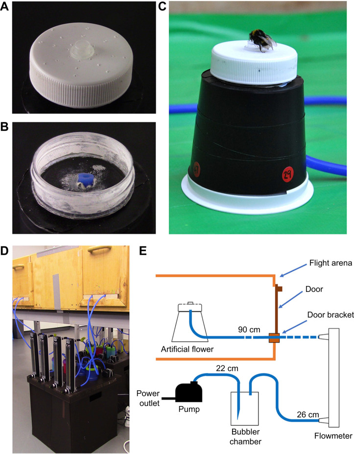
Fig. 1.
The active artificial flowers used in bumblebee experiments. (A) The artificial flower head. Note the holes on the flower head for air to escape. (B) The flower head with the head unscrewed, allowing the chamber under and pipe entry point to be seen. (C) A bumblebee feeding from active humidity flower as they appear in the flight arena. (D) The pump–bubbler–rotameter assembly installed below the flight arena. Note the rubber tubes entering the arena through brackets below the doors. (E) A diagrammatical representation of each artificial flower and its pump mechanism and how it is installed through the flight arena through a door bracket. Rubber tubes are represented by blue lines connecting components; the lengths of tubes are given above each tube.

