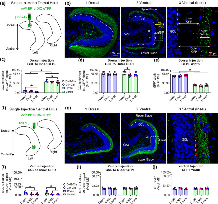
FIGURE 5.

Quantitative analysis of the GFP+ MC axon terminal plexus. (a) Schematic showing that AAV‐EF1a‐DIO‐eYFP was injected into the left dorsal hilus. (b1–b2) A representative example of contralateral GFP+ axon terminals in the (b1) dorsal and (b2) ventral DG of a female Crlr‐Cre+/− mouse. The width of the molecular layer (ML) is depicted by the yellow arrow and the approximate subdivisions of the inner (I), middle (M), and outer (O) are separated by dashes. (b3) A schematic shows the inner, outer, and width measurements for the GFP+ axon plexus. Measurements were made in the center of the upper blade, crest, and center of the lower blade and reported as a % of total ML width. (c) In dorsally injected mice, the GFP+ axon was near the GCL/IML border in dorsal sections, but primarily in the MML of ventral sections. Blue and pink data points represent male and female mice, respectively. (d) The outermost distance of the GFP+ axon was approximately 63–64% of dorsal and ventral sections, indicating the GFP+ axons primarily terminated in the MML. (e) The total width of the GFP+ axon was significantly greater in dorsal than ventral sections. (f) A schematic for additional animals where AAV‐EF1a‐DIO‐eYFP was injected into the left ventral hilus. (g1–g2) A representative example of contralateral GFP+ axons in the relatively (g1) dorsal and (g2) ventral DG of a male Drd2‐Cre+/− mouse. (g3) A schematic showing GFP+ axon measurements. (h) The inner distance did not differ between dorsal and ventral sections, but the parts of the DG differed. (i,j) The outer GFP+ distance and total GFP+ width did not differ between dorsal and ventral sections. Notably, all measurements from ventrally injected mice were below 33%, indicating the axon was restricted to the IML. *p < .05 [Color figure can be viewed at wileyonlinelibrary.com]
