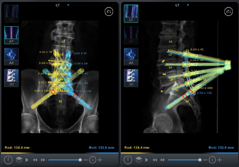
Fig. 2.

Mazor X software robotic plan showing planned screw trajectories from L3 to S2AI, as well as the marked disc space levels from L3–4 to L5–S1. Note that the cortical lumbar screws line up well with the S2AI screws for a straight planar rod design.
