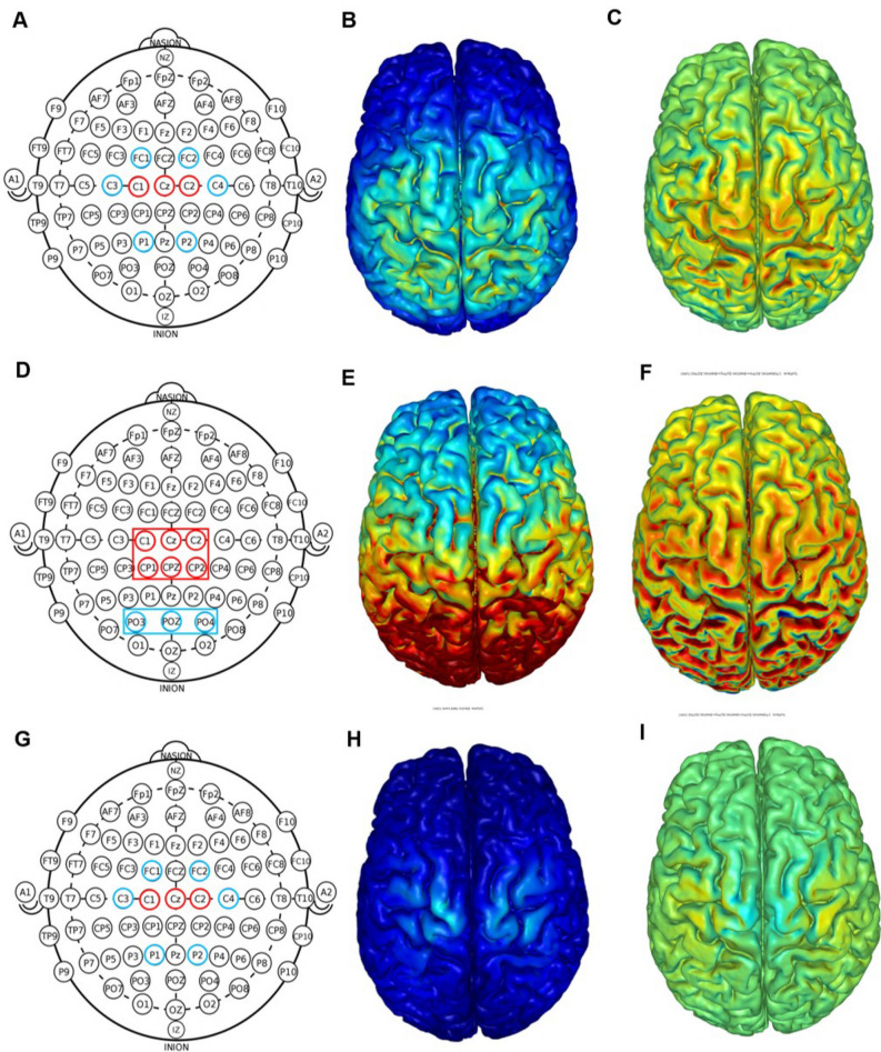
Figure 2.
Transcranial direct current stimulation montages used in the present study: high-definition (top row), simulated conventional (middle row), and active sham (bottom row). Ring electrode positions (red = anodal electrode; blue = cathodal electrode) according to the EEG 10/20 system (A, D, G). For the conventional montage, ring electrodes were used to simulate the rectangular electrodes (D). Computational modeling of the finite element model of the total (B, E, and H) and radial (C, F, and I) electric fields induced by high-definition and active sham tDCS. All figures are displayed with a field intensity of 0.30 V/m (directionless. blue = zero electric fields; red = peak magnitude). Radial electric field (C, F, and I) considers the direction of current (blue = peak outward current; green = zero normal current; red = peak inward current). Note: panels B, C, E, F, H, and I was generated by the HD-Explore software (Version 2.3, Soterix Medical, New York, NY; https://soterixmedical.com/research/software/hd-explore).

