
Figure 3.
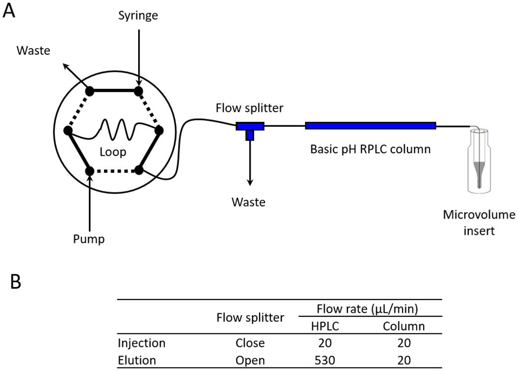
A flow splitter implemented in microscale HPLC. (A) Integrated scheme including a sample loading loop, HPLC pump, a reverse-phase LC column, and one flow splitter with a waste line (63.5 μm i.d. x 60 cm tubing). The pooled TMT sample was first loaded onto a 20 μl sample loop, and injected to the column at flow rate of 20 μl/min for 20 min with the splitter closed. After injection, the sample was eluted with the splitter open, which allowed for 20 μl/min column flow rate using 530 μl/min HPLC flow rate. (B) The flow rates with the flow splitter at different positions.