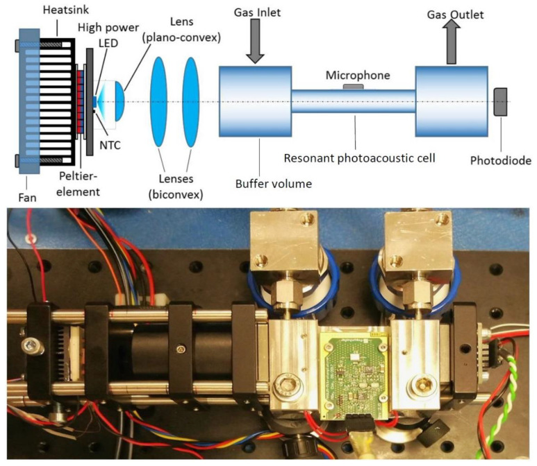
Figure 3.
Setup of the developed resonant photoacoustic gas sensor. The upper part of the figure shows the sensor components in a schematic drawing. The sensor consists of the resonant photoacoustic cell with the MEMS microphone at the center of the resonator. The gas inlet and outlet are placed at the buffer volumes. The temperature of the high-power ultraviolet (UV) light-emitting diode (LED) is controlled via a thermoelectric cooler and a thermistor. The light beam is focused by optical lenses, which increases the sensitivity of the sensor system. An additional photodiode monitors the LED performance. The lower part of the figure is a photo of the corresponding developed sensor system [16].

