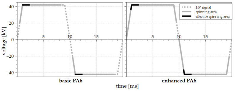
Figure 5.
The AC electrospinning processes driven by the step change signal for the basic PA 6 solution (left) and the enhanced solution (right). The voltage signals are represented by the dotted gray lines, the spinning areas are shown as solid gray lines, and the effective electrospinning areas are highlighted by the solid black lines. The rising slope time was 1 millisecond.

