
Figure 5. Site 3 and C-terminus stabilization.
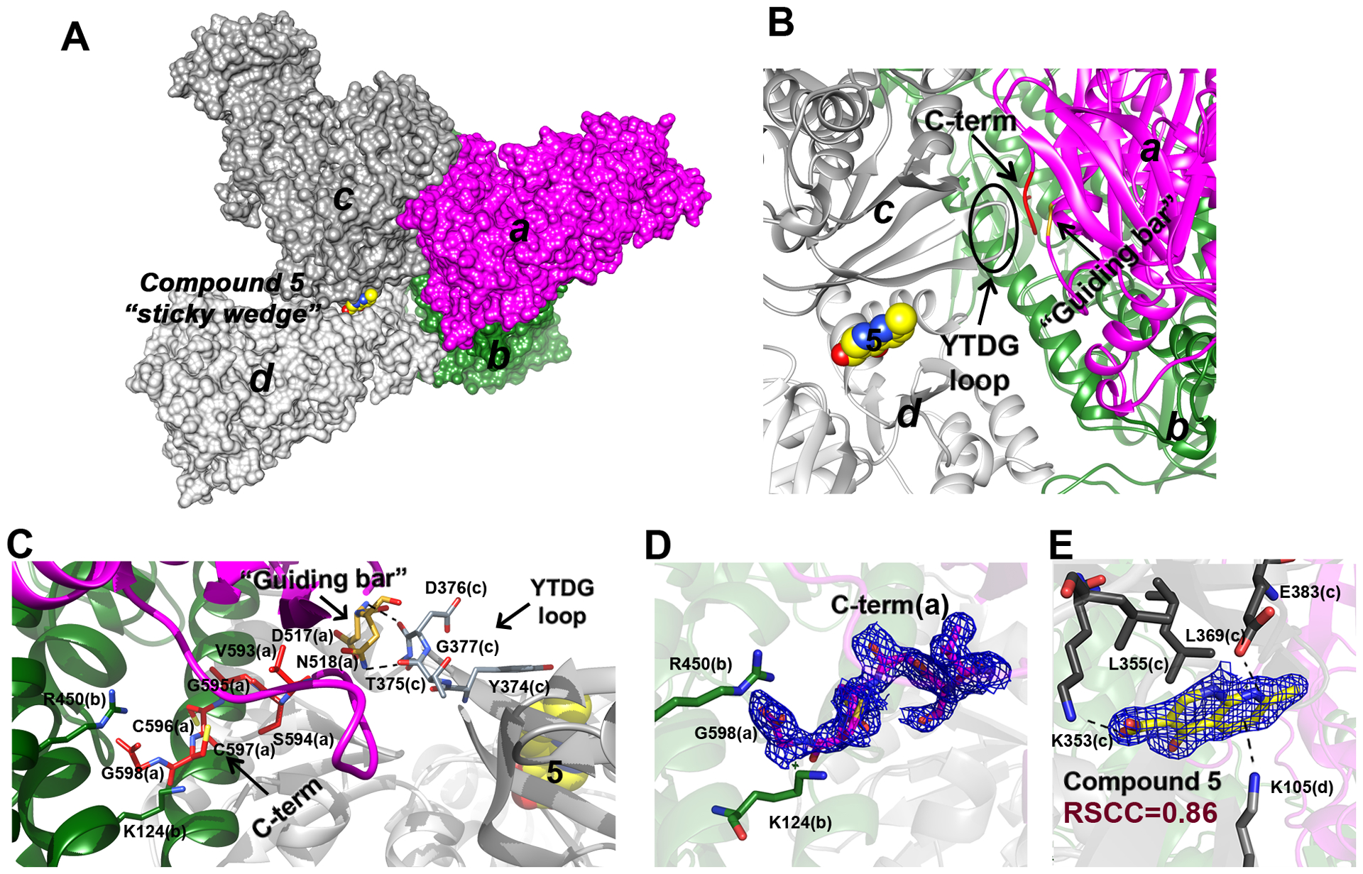
A. A subset of SmTGR subunits, “a” (in magenta), “b” (in deep green), “c” (in dark grey) and “d” (in light grey) as visualized in the crystal lattice of SmTGR in complex with 5 in Site 3, are shown as solvent-exposed surface. Subunits “a” and “b” belong to a physiological SmTGR dimer, while “c” and “d” belong to different physiological dimers. Compound 5 fits between subunits “c” and “d” as a sticky wedge. B. The relative position of 5, with respect to the YTDG loop of subunit “c”, to the guiding bar and to the C-terminus of subunit “a” is depicted. C. The YTDG loop of subunit “c”, the guiding bar residues (D517 and N518) and the last 6 residues of the C-terminus (V593-G598) of subunit “a” are shown in sticks. Dotted lines represent H-bonds between the YTDG loop and the guiding bar and between the guiding bar and the C-terminus (see main text). D. The 2Fo-Fc electron density of the C-terminus of subunit “a” is shown together with the R450 and K124 of subunit “b” (in sticks) that sandwiched the G597 carboxylate. E. The 2Fo-Fc electron density of 5 (here in yellow sticks) and its contacting residues (in grey sticks) belonging to “c” and “d” subunits are shown.