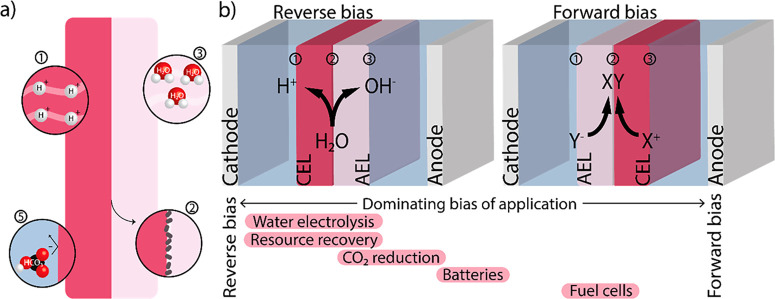
Figure 1.
(a) Schematic of components of an ideal bipolar membrane (BPM), with (1) high conductivity of the individual bulk layers, (2) fast chemical kinetics at the interface via deposition of catalyst, (3) high water permeability, (4) long lifetime under operational current densities (not shown here), and (5) low ion crossover. (b) The BPM can operate in two modes: reverse and forward bias. A BPM comprises three interfaces of interest: two with the electrolyte/electrode and membrane layer (1 and 3) and one between the membrane layers (2). At each interface, a potential difference is created due to the change in charge density, as described in the literature.17,18 A BPM can also be used in a zero gap configuration (not shown here), in which the membrane layer is in contact with the electrode. The bars at the bottom of the image indicate the different applications and their relative usage of each orientation (e.g., water electrolysis is only performed in the reverse bias orientation, while CO2 reduction is predominantly used in reserve bias but has also been studied in forward bias).

