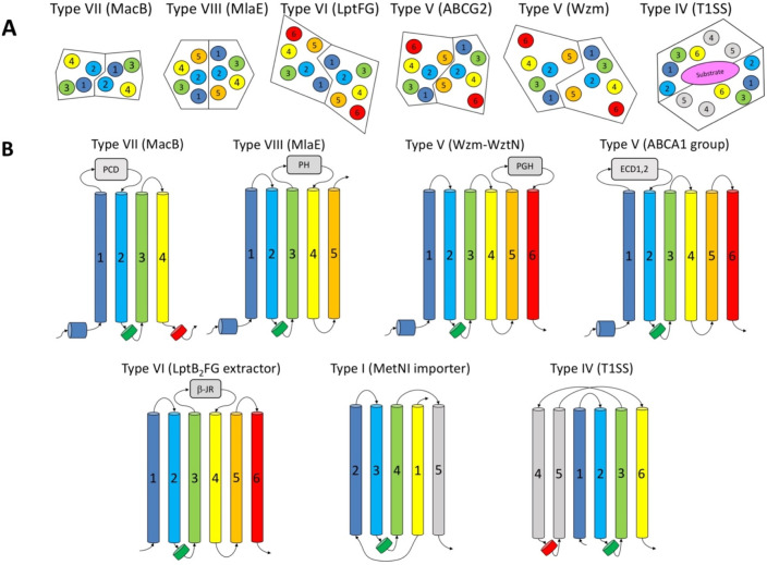
Figure 26.
(A) Schematic representation of the TM helix packing at the dimer interface between different classes of ABC transporters shows close connections of the MacB architecture to the type VI and type VIII (MlaEF) transporters. Topologies are derived from the structures of MacB (PDB ID 5GKO),24 MlaE (PDB ID 6XBD),439 LptB2FGC complex (PDB ID 6S8N),635 Wzm-WznT (PDB ID 6M96),429 and ABCG2 (PDB ID 5NJG).632 Top-down view from the periplasm. Note: due to the intertwisting of the helices in the type IV transporters, the diagram depends on the level at which the slice is cut through the TM; the provided view is representative to the middle of TM segment, based on the ABCB1 structure (PDB ID 6QEX).521 (B) Topological connections within the ABC transporter families. The ABC transporter families share a common core architecture, which can be derived from the four TM helices seen in the type VII (MacB/FtsX) family. The other main families of exporters are presented, which could be seen as derived from MacB by addition of C-terminal helical fragments. Homologous helices are colored consistently from the N-terminal to the C-terminal. The intracellular coupling helices (CH1 and CH2) are presented in green and red. CoH = connecting helix. Substrate binding domains are shown as gray boxes (PCD, periplasmic core domain; PH, pore helix; PGH, periplasmic gate helix; ECD1,2, extracellular domains 1, 2; β-JR, β jelly roll domains). Adopted with modifications based on Schaeffer et al.634

