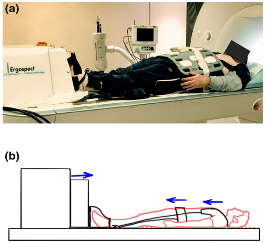
FIGURE 1:

Experiment setup. (a) is the photograph of the experimental setup used for mechanical loading during the magnetic resonance imaging (MRI) scan, and (b) is the schematic of the experimental setup showing how the mechanical load is transferred to the spine. Standing mechanical load is applied at the foot using an ergometer, while the volunteer movement is restricted using a harness that distributes the fixation pressure to the waist and shoulders.
