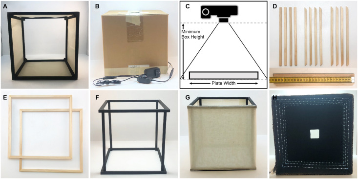
FIGURE 1.
Components and construction of the imaging box. (A) Light diffusing component of the imaging box that is open on the top and the bottom (side view). (B) Light box component of the imaging box that eliminates unwanted light and glare while providing lighting for imaging. (C) Determining the necessary height for the imaging box. (D) Twelve square wooden dowels cut for the construction of the light diffuser, eight cut with 45° angles and four cut with 90° angles. The measuring tape on the bottom indicates dowel length in centimeters. (E) The top and bottom frames of the light diffuser constructed using the eight wooden dowels cut with 45° angles. (F) The assembled diffuser frame painted matte black. (G) The completely assembled diffuser. (H) The inside of the light box showing the LED light strip on the sides of the box, the matte black interior, and the square hole in the top of the box.

