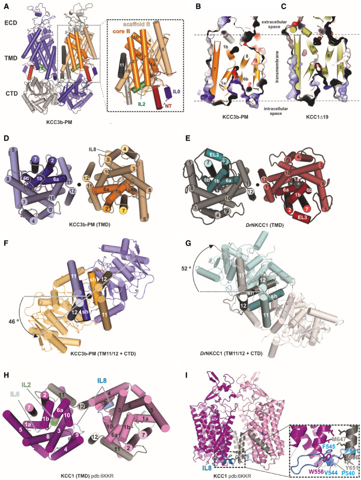
Figure EV1. TMD and CTD arrangement in KCC1Δ19 and KCC3b‐PM, in comparison to DrNKCC1 and CTD‐free KCC1 (Related to Fig 1).

-
ACartoon representation of the KCC3b‐PM dimer with inset illustrating the TMD of one subunit. The transporter core domain is shown in orange, the scaffold domain in wheat.
-
B, CSlab view of the transporter domain of KCC3 (construct: PM) (B) and KCC1 (construct: Δ19) (C) in surface representation, highlighting the inward‐open conformations with intracellular accessible vestibules.
-
D, EExtracellular view of the TMD dimer of KCC3b‐PM (D) and DrNKCC1 (E).
-
F, GExtracellular view onto central TM11/TM12 helices and CTD, highlighting counter‐clockwise twisted CTD for KCC3b‐PM (F) and clockwise twisted CTD for DrNKCC1 (G).
-
HExtracellular view onto TMD dimer illustrating the alternative dimer interface observed in CTD‐free KCC1 (6KKR).
-
IFront view on CTD‐free KCC1 dimer detailing molecular interactions (inset) between IL8 (blue helix) and TM12 characteristic for the configuration in 6KKR.
