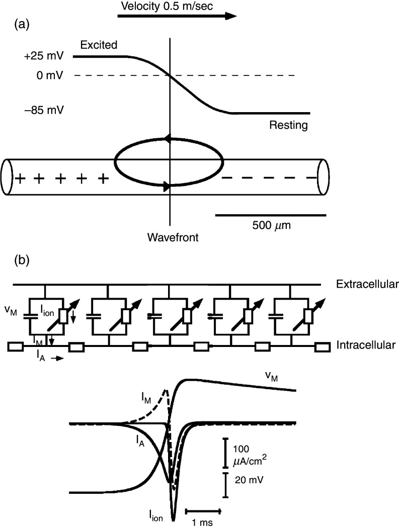
FIG. 8.
Linear excitable cable [panel (a)] and ion current flow [panel (b)] in one excitable element. Panel (a): Cylindrical excitable cable showing propagating wavefront with an upstream excited segment and downstream resting segment. The excited segment has a positive membrane potential (voltage difference between the inside of the cellular compartment and the outside reference). The downstream non-excited portion has a negative membrane potential. A loop of so-called “local current” or electrotonic current is set up and acts to excite the downstream segment and to propagate the electrical impulse. Of note, the electrical resistivity of the inside medium is not re-partitioned into cytoplasmic and cell-to-cell resistance in this model. Panel (b): An electrical equivalent circuit of a continuous model is depicted on the top with five excitable elements residing in the cell membrane. The intracellular space is represented by a single resistor. The exchange of electrical charge is shown on the lower part. Axial current, IA, initially flows from upstream sites into the membrane. During this phase, membrane current, IM, shifts the membrane potential, VM, to more positive values, toward the threshold of Na+ inward current. The subsequent peak and rapid change of IM reflects the activation of Na+ channels, illustrated by Iion. Flow of ionic current, Iion, charges the membrane capacitance, thereby producing the action potential. It also changes the sign of flow of the axial current, which now represents charge furnished by channel excitation and flowing into the downstream sink.

