
Fig. 1. Schematics of refraction of polaritons between two hyperbolic media.
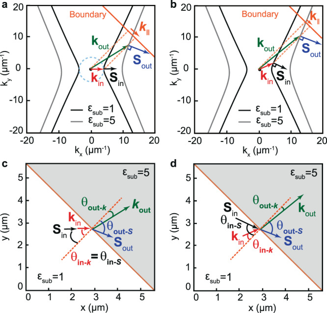
a Isofrequency curves of polaritons propagating in a hyperbolic slab (with εx = −5; εy = 1; εz = 5) placed on two different semi-infinite substrates with = 1 (black curve) and = 5 (gray curve) that define two different hyperbolic media (medium 1 and 2, respectively). The incident wave in medium 1 is characterized by collinear and (as in an isotropic medium, indicated by a dashed cyan circle). Upon refraction into medium 2, momentum conservation at the boundary (orange line), (, where is the angle of the boundary), is fulfilled by non-collinear and . The dashed orange lines represent the normal to the boundary. b The general case of refraction between two hyperbolic media is represented by an incident wave from medium 1 with non-collinear and (normal to the isofrequency curve). When the wave refracts into medium 2, momentum conservation at the boundary (orange line) is fulfilled by non-collinear and . The dashed orange lines represent the normal to the boundary. c Real-space illustration of refraction between two hyperbolic media shown in a where the incident wave exhibits collinear and , i.e. , giving rise to non-collinear and , i.e. ≠ . d Real-space illustration of the general case of refraction between two hyperbolic media shown in b where both the incident and the outgoing wave exhibits non-collinear k and S, i.e. and ≠ . The tangents parallel to both hyperbolas give rise to bending-free refraction, i.e. . The orange dashed lines in c, d represent the normal to the boundary. The white and gray regions in c, d correspond to α-MoO3/air and α-MoO3/SiO2, respectively.