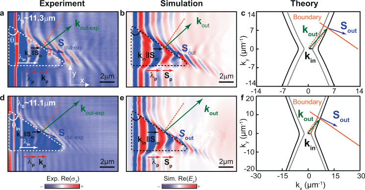
Fig. 2. Real-space visualization of refraction between two anisotropic media using highly confined polaritons with collinear incident k and S.
a, b Experimental (a) and simulated (b) near-field images of HPhPs propagating in a 160-nm-thick α-MoO3 flake at = 11.3 μm. The white and black dashed lines mark triangular prisms fabricated by etching an air cavity on the SiO2 substrate below the α-MoO3 flake. and display the direction of propagation and the wavevector of incident polaritons in α-MoO3/air, respectively. Horizontal propagation of non-refracted polaritons is marked as and . Upon refraction at a boundary of the prism with an angle ~ 55°, HPhPs bend away from the normal, (blue arrow), with a tilted wavevector (green arrow). Compared to non-refracted HPhPs, indicated by , the refracted HPhPs are stronger confined (with a wavelength about 1.6 times shorter. c Analytic IFCs of α-MoO3/SiO2 (black hyperbolas) and α-MoO3/air (gray hyperbolas) effective media in a, b, and considering momentum conservation at the boundary (orange line), the extracted wavevector and direction of the refracted polaritons, and , respectively, are in good agreement with both experiment and simulation. d, e Experimental (d) and simulated (e) near-field images of HPhPs propagating in a 160-nm-thick α-MoO3 flake at = 11.1 μm. The refracted HPhPs propagate almost parallel to the boundary with a wavelength 2.1 times smaller than . f Analytic IFCs of α-MoO3/SiO2 (black hyperbolas) and α-MoO3/air (gray hyperbolas) effective media in d, e. The orange dashed lines in a–f represent the normal to the boundary.

