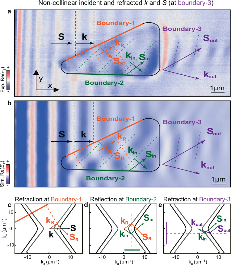
Fig. 4. Real-space visualization of the general case of refraction between two anisotropic media using nanoscale-confined HPhPs passing through a bending-free planar prism.
a Experimental near-field images of polaritons propagating in a 231-nm-thick α-MoO3 flake at = 11.0 μm. The black contour line marks a triangular prism fabricated by etching an air cavity on the SiO2 substrate below the α-MoO3 flake. A first refraction takes place at boundary-1 (orange solid line) for incident polaritons with collinear and (black arrows), yielding refracted polaritons with non-collinear and (orange arrows). These polaritons then reflect at boundary-2 (green solid line), yielding polaritons with non-collinear and (green arrows). A second refraction at boundary-3 (violet solid line) yields polaritons with non-collinear and (violet arrows). b Simulated near-field images of HPhPs for the case shown in a. Dashed lines in experimental and simulated near-field images indicate the wavefronts of polaritons as they pass through the prisms. c–e Analytic IFCs of HPhPs in MoO3/air (gray curve) and MoO3/SiO2 (black curve), predicting the directions of refraction or reflection of HPhPs at boundary-1 (c), boundary-2 (d), and boundary-3 (e) based on momentum conservation. The orange (c), green (d), and purple (e) solid lines represent the boundary-1, boundary-2, and boundary-3, while the corresponding dashed lines represent the normal to the boundary.

