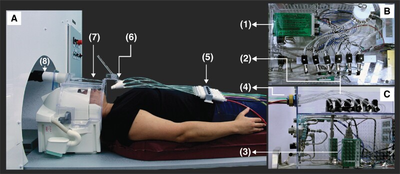
Figure 1.
Odor canopy setup overview. Odorant delivery setup from (A) side view of scanner-bed, (B) top view in control room, and (C) side view in control room. Setup is composed of a (1) control board, controlling (2) 6 solenoids and (3) MFC, with airflow lines connecting the MFC to the solenoids and from solenoids to (4) 8-female connector. Colored braided tubes were connected from this connector to (5) Teflon canisters within Teflon odorant cassette placed over the participant’s torso. The outputs of the Teflon canisters were connected to a (6) 6-port nozzle, which directed to the participant (7) headspace. Air was (8) vacuumed out constantly using a vacuum located outside the scanning room. This allows ongoing airflow with added odorants imbedded at high temporal resolution.

