Figure 6.
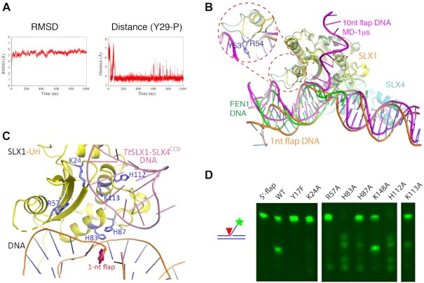
Recognition of the 5′-flap by the SLX1–SLX4 complex. (A) MD simulation of a 10-nt 5′-flap DNA bound to the SLX1–SLX4SAP+CCD complex. The RMSD values and the distances between the catalytic Tyr29 and the neighboring DNA backbone phosphate during the course of 1 μs simulation are shown. (B) A representative model from the MD simulation (SLX1 in pale green, SLX4 in light blue, and DNA in magenta) shows that the 5′-flap binds SLX1 in a shallow cleft flanked by positively charged residues (also see Supplementary Figure S10). The crystal structure of the SLX1–SLX4SAP+CCD–DNA complex (SLX1 in yellow, SLX4 in cyan and DNA in orange) and the 5′-flap DNA substrate of FEN1 (green) are superimposed. The conformation of the pre-nick DNA from the MD simulation appears more similar to that of FEN1 DNA. The inset shows that the loop connecting α1 and β3 is capable of binding DNA, as demonstrated by the indicated residues in contacting the major groove of DNA. (C) Superposition of the hairpin DNA from the TtSLX1–SLX4CCD–DNA complex (pink; PDB ID: 6SEI) onto the ScSLX1–SLX4SAP+CCD–DNA structure. Selected positively charged residues are shown in a stick representation. For visual clarity, SLX4 is not displayed. (D) Mutations of selected residues in the newly identified DNA binding region of SLX1Uri differentially affect the 5′-flap cleavage activity of the SLX1–SLX4SAP+CCD complex.

