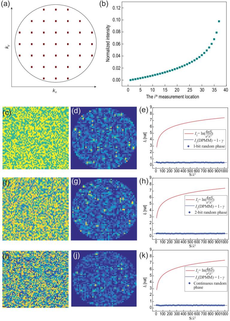
Figure 5.

(a) A set of measurement locations in the  space with M = 37. (b) Theoretical intensity distributions of the measurement points. (c, d) A sample of 1-bit disordered-phase pattern of the metasurface and the generated far-field intensity distribution. (e) Theoretical and calculated results of I2 with respect to different sizes and phase patterns of metasurfaces. (f, g) A sample of 2-bit disordered-phase pattern of metasurface and the generated far-field intensity distribution. (h) Theoretical and calculated results of I2 with respect to different sizes and phase patterns of metasurfaces. (i, j) A sample of continuous disordered-phase pattern of the metasurface and the generated far-field intensity distribution. (k) Theoretical and calculated results of I2 with respect to different sizes and phase patterns of metasurfaces.
