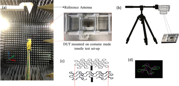
Figure 5.
(a) Experimental setup for radiation pattern measurements inside the anechoic chamber (left). Broadband (0.5 MHz–18 GHz) dual polarized log periodic antenna was used as reference. The inset image on the right shows the fully meshed microstrip antenna mounted on the custom-made setup in zero strain condition. (b) 2D DIC setup with horizontal tripod arm. The optical axis of the camera is aligned perpendicular to the sample surface to avoid errors in the image correlation. (c) Representative serpentine unit cell of the patch. Purple contour shows an undeformed shape while green one shows the corresponding contour for 40% of strain. (d) CAD schematic representing the surface morphology of the patch in 0% and 40% of strain.

