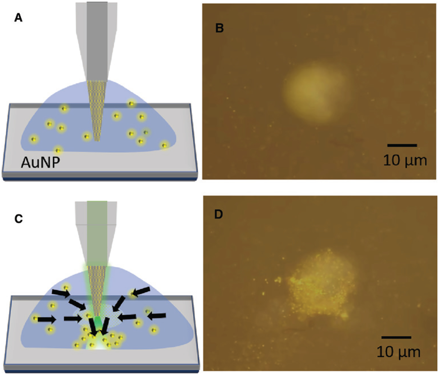
Figure 3: OTFT nanoparticle concentrator.

(A) Schematic of the multimode tapered-OTFT immersed in the 200 nm Au nanoparticles (AuNP) solution. (B) Microscope image of the fabricated multimode tapered-OTFT (normal mode operation) immersed in 200 nm Au nanoparticle solution with no output optical power. The image is obtained by focusing the objective lens on the top surface of the glass coverslip with the tapered-OTFT tip placed 20 μm above the glass surface. (C) Schematic of the multimode tapered-OTFT with 10 mW of output power. The arrows demonstrate the flow of nanoparticles toward the tapered fiber due to the convective flow and then directed toward the glass surface. (D) Microscope image of the multimode tapered-OTFT showing the concentration of 200 nm Au nanoparticles on the glass surface 16 s after the laser is turned on.
