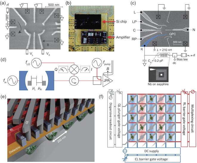
Figure 6.
Approaches to improve readout quality and a crossbar network for large-scale integration. (a) SEM image of a device using an rf-QPC, indicating ohmic contacts (boxes), fast gate lines, impedance-matching circuit, grounded contacts, and the external magnetic field direction. (Adapted from [145].) (b) Picture of a silicon device with an adjacent cryogenic amplifier circuit mounted on printed circuit board. (Adapted from [150].) (c) False-color SEM image of a device using an rf gate sensor. One electrode (blue) is coupled directly via a bondwire to an off-chip Nb/Al2O3 superconducting lumped-element resonator. (Adapted from [152].) (d) Diagram of the device using a distributed superconducting resonator with the input field  . The output field is sent to a JPA through a circulator and then demodulated into the I and Q quadratures with a local oscillator tone
  . A directional coupler is used to couple the pump field at frequency
  (Adapted from [158].) (e) and (f) are a 3D model and schematic representation of the crossbar network for a 2D quantum-dot array. CLs (blue), RLs (red), and QLs (gray) connect the qubit grid to outside electronics for control and readout [39].

