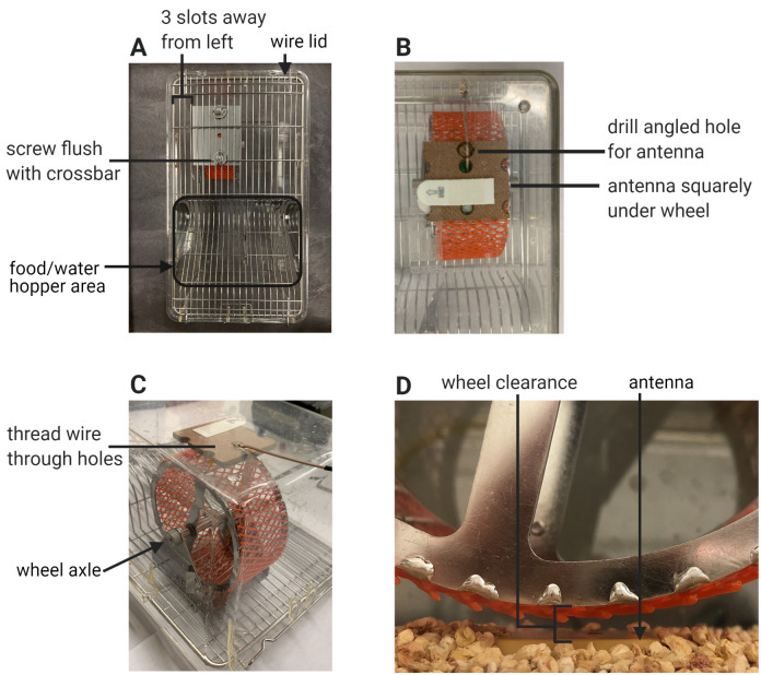
Figure 3. Cage setup.
A. Proper assembly of the wheel housing in relation to the wire lid and cage layout. B. Bottom-up view of the Techniplast cage showing the area under the wheel. Proper placement of the antenna and pegboard square under the wheel. The drill site is adjacent to the wire exit hole of the pegboard and is indicated by the black circle drawn on the cage bottom. C. Threading of the antenna wire through the cage hole. D. Clearance between the antenna and the wheel.

