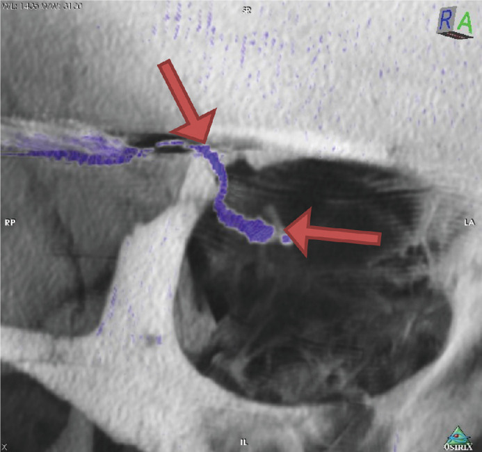
Figure 3.

Arrows indicate the straight cable route between the two fixation points of the silicon cable, one at the orbital rim and the other at the fixation pad of the implant. The majority cable movements during eye movement and therefore the maximal mechanical stress acting on the cable occurs there (Subject RIAG TU02).
