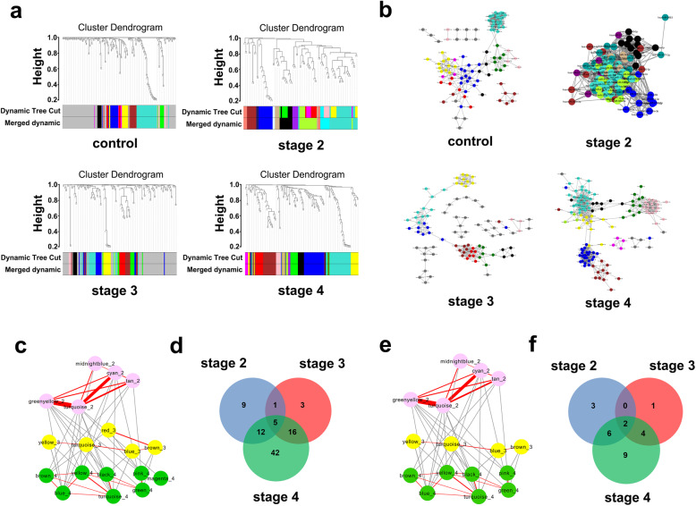
Fig. 3.
WGCNA of differentially expressed miRNAs in each stage. a Module clustering trees of control, stage II, stage III and stage IV constructed with differentially expressed miRNAs in each stage. Color indications as in Fig. 2. b The module network diagrams of control and stages II–IV obtained from the module clustering trees of a, by Cytoscape visualization. Different colors represent different modules. Different topological overlap thresholds were selected at different stages according to the size of the network and its accuracy, which were 0.05, 0.43, 0.05 and 0.05, respectively. Dark gray dots represent miRNAs that were not assigned to any module. c Enriched modules of stage II (pink), stage III (yellow) and stage IV (green) after functional enrichment analysis. The red line segment represents the module connections within the stage. The strength of connection between different modules is expressed by the thickness of the line, with a higher thickness indicating a higher strength of connection. d Venn diagram of contained miRNAs in modules of c. e HMDD-aligned modules of c. f Venn diagram of miRNAs contained in modules in e

