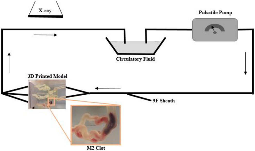
Figure 2:

Schematic representation of the clot model. The model contains separate inflow and outflow channels and is connected to a pulsatile pump via a closed circuit. Arrows indicate direction of flow. A 9 F sheath allows the introduction of guide catheters and thrombectomy devices. Biplane angiography is used during thrombectomy experiments. A zoomed in image of the 3D printed model displays a clot located within the M2.
