. 2020 Nov 10;50(1):556–568. doi: 10.1039/d0cs00855a

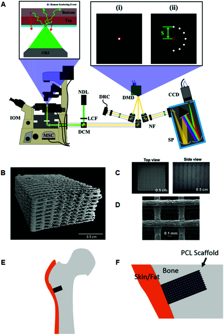
Fig. 3. Representative images of 3D printed bone scaffolds. (A) Graphical drawing of the DMD-based SORS instrument used to image the bone scaffolds. Abbreviations are as follows; OBJ, objective; IOM, inverted optical microscope; MSC, microscope side-port camera; DCM, dichroic mirror; LCF, laser clean filter; NDL, 20 mW, 532 nm Nd:YAG diode laser; DMD, digital micro-mirror device; DRC, DMD inspection camera; NF, notch filter; SP, spectrometer; CCD, charge couple device detector. The red circles in the magnified images (i) and (ii) refer to the position corresponding to the focused laser on the sample, and on the sample-conjugate plane of the DMD (equivalent to a zero spatial offset). (i) Displays a DMD pattern for a standard confocal Raman measurement and (ii) shows a possible SORS configuration. (B) Micro-CT 3D reconstruction image of polycaprolactone (PCL) and hydroxyapatite (HA) scaffold PCL : HA 1 : 4 with dimensions 10 × 10 × 5 mm, porosity = 64.7%. (C) Images from dissecting microscope of a PCL : HA (1 : 4) scaffold (D) scanning electron microscopy of a PCL : HA scaffold with 1 : 2 blend ratio. (E) Conceptual diagram of the head of a femur with a critical defect drilled into it. The scaffold is then inserted into the defect. (F) Conceptual close up of the bone defect filled with a PCL scaffold. Adapted from ref. 83 and 84 with permission from The Optical Society, copyright 2016 and 2019.

Fig. 3