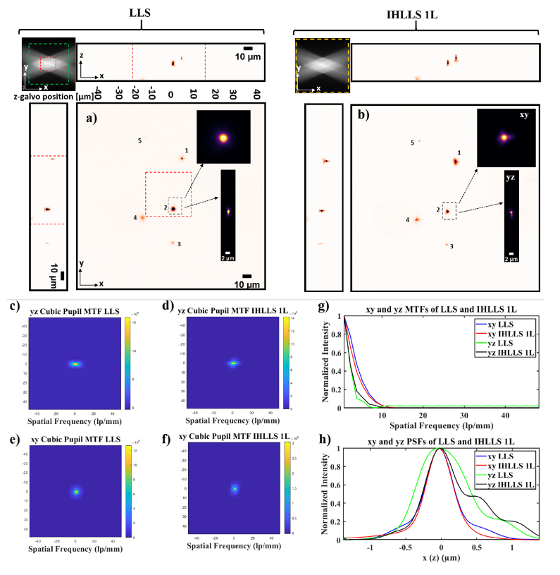
Fig. 3.
Tomographic imaging of 0.5 µm, FOV 208 µm2, in a conventional LLS (a) and incoherent LLS with only one diffractive lens (IHLLS 1L) of focal length 400 nm (b), without deconvolution. On the sides and above are shown the max projections through the volume (400 Z-galvo steps). The Bessel beams are displayed in the upper left corner of each xy-projection to show the orientation of the beams (FOV 208 µm2) . The area enclosed inside the colored dashed rectangles are as follows: red- the scanning area for the original LLS (52 µm^2), green – the extended area mentioned in [21] of 120 µm^2, and yellow – the actual scanning area for the LLS, IHLLS 1L, and IHLLS 2L. The bead #2 in the black dashed rectangle that is in the middle of the lattice sheet is considered for calculating the resolution for the two instruments. The transverse MTFs of the two imaging techniques are shown in (c, d) and the axial MTFs are shown in (e, f); g) 1D xy and yz sections of the MTFs, h) 1D xy and yz of the PSFs. The FWHM of the curves are blue- 0.530 µm, red 0.495 µm, green 0.8341 µm, and black 0.9004 µm.

