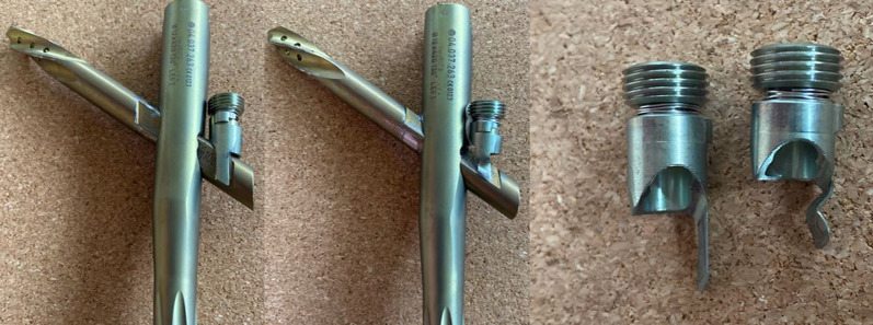
Fig. 8.
Far left, the helical blade has been inserted correctly so that the orientation of the recess on the side of the helical blade docks with the locking prong correctly and allows the set screw to be seated fully. Pictured middle, with an under-inserted helical blade, this recess is no longer aligned with the trajectory of the set screw. In this scenario, the set screw will advance until the lock prong contacts the superior aspect of the blade/screw resulting in deformation. Pictured right, a comparison of an intact locking prong and a deformed locking prong

