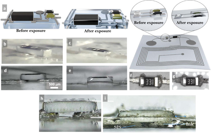
Fig. 4. Details of the self-soldering process.
a A schematic presentation of the microchip integration into the soft-matter circuit before and after exposure. Snapshot of a resistor component before (b) and after vapor exposure (c). Note the penetration of the component and the ink into the substrate. Side view of a resistor chip before (d) and after (e) vapor exposure. The light reflection of the chip after exposure shows the SIS that climbed the walls of the chip due to capillary action. Top view of the resistor chip before (f) and after (g) vapor exposure. The color difference of the ink demonstrates encapsulation. Magnified side view of the resistor chip before (h) and after (i) vapor exposure. All of the ink and approximately half of the resistors are inside the substrate. Note also the SIS below the resistor and on the sides.

