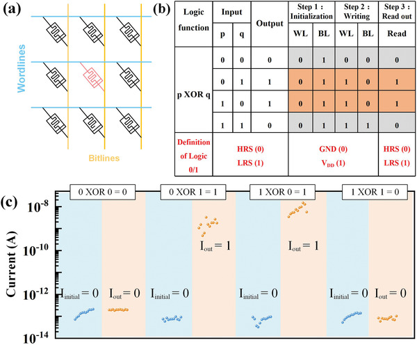
Figure 6.

a) Schematic of the logic circuits. WL is connected to the top electrode and BL is connected to the bottom electrode. b) XOR logic and operation steps are shown in the truth table. c) Experimental results of XOR logic operations with the reading voltage of 0.1 V.
