Figure 1.

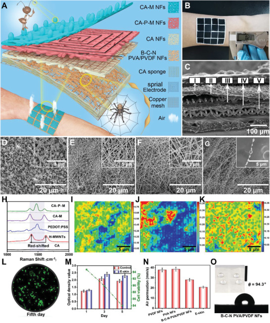
Structure, composition, biocompatibility, and air permeability of e‐skin device: A) Schematic illustration of a 4 × 4 pixels e‐skin. Insets: Partially enlarged view of a single e‐skin pixel. B) Optical photograph of a 4 × 4 pixels e‐skin conformably attached on the arm. The inset is an optical image of e‐skin's thickness. C) SEM image of the cross section of e‐skin (I, II, III, and IV corresponding to D, E, F, and G, and V is copper mesh. D–G) SEM images of CA‐M NFs, CA‐P‐M NFs, CA NFs, and B‐C‐N PVA/PVDF NFs. The inset SEM images show the details separately. H) Raman spectrum of the CA, H‐MWNTs, PEDOT:PSS, CA‐M NFs, and CA‐P‐M NFs. I,J) Raman mapping images of PEDOT:PSS and MWNTs in CA‐P‐M NFs. K) Raman mapping image of MWNTs in CA‐M NFs. L) Photomicrograph of the cell density on the 5th day of the MTT assay of the e‐skin. M) Optical density value and cell viability in MTT test of control and e‐skin. N) The air permeability of e‐skin and its different layers. O) Image of water contact angle of B‐C‐N PVA/PVDF NFs. Inside is an optical image of water droplets resting on B‐C‐N PVA/PVDF NFs.
