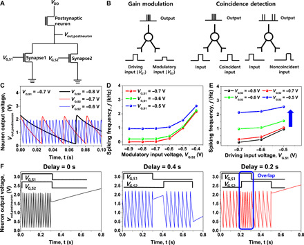
Fig. 4. Gain modulation and coincidence detection by cointegrated single-transistor neuron and synapses.

(A) Circuit diagram of connected two transmitting synapses and one postsynaptic neuron for gain modulation and coincidence detection. (B) Schematic diagram of gain modulation and coincidence detection. Neuronal output can be determined by the modulatory input as well as the driving input, and the coincidence of the two inputs can be detected from the neuronal output. (C) Spiking characteristics of the postsynaptic neuron depending on the modulatory input voltage (VG,S2) when the driving input voltage (VG,S1) was fixed. The spiking frequency (f) was increased as the VG,S2 was increased because the input current to the postsynaptic neuron was increased. (D) f as a function of the VG,S2 at various VG,S1. (E) f as a function of the VG,S1 at various VG,S2. It showed a shift in the vertical direction, which is a typical additive operation of output modulation. (F) Spiking characteristics of the postsynaptic neuron depending on the delay between the two signals. f was larger when two signals became more synchronized. When two signals overlapped for a certain period of time, the f was increased only in the overlap region.
