Figure 2.
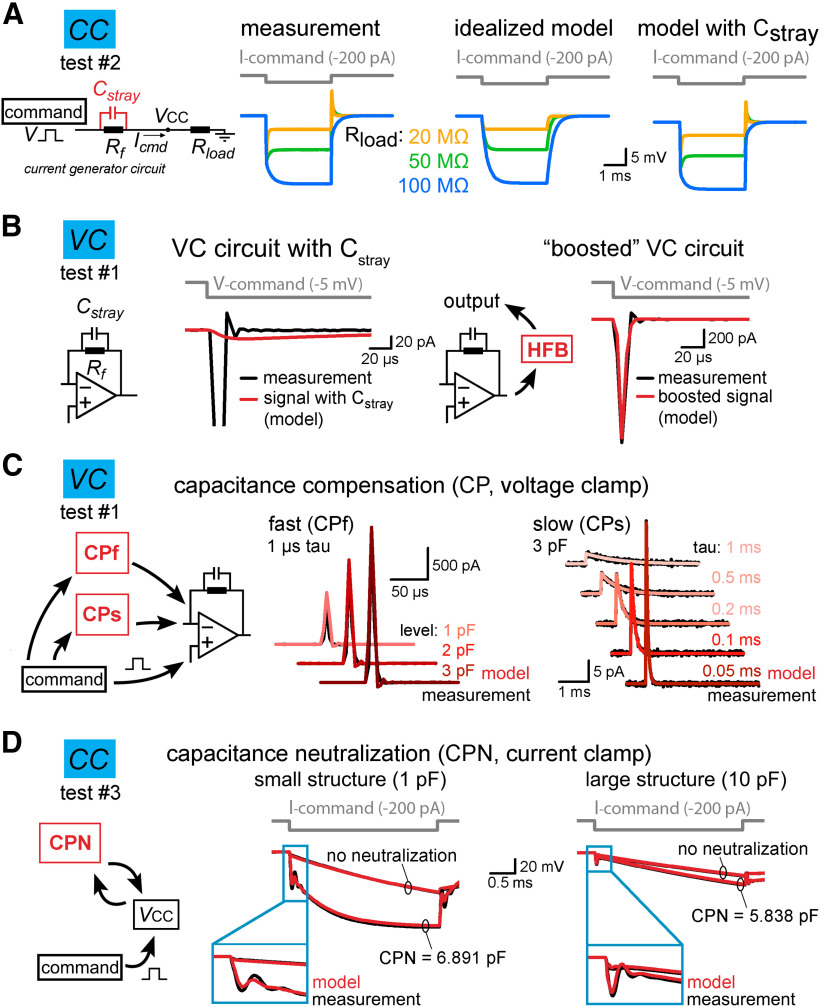
Implementation of individual amplifier components with realistic parameters. A, The stray capacitance (Cstray) associated with the current passing resistor (Rf) was predicted by simulating the voltage responses recorded in test #2 configuration. Cstray acts as a capacitance neutralizing element in CC mode. Because the capacitance neutralizing effect of Cstray depends on the load resistance (Rload) attached to the amplifier input (VCC), we tested three scenarios using 20-, 50-, and 100-MΩ resistors. The left traces show measured voltage responses evoked by brief current injection in the presence of different Rload. Idealized (i.e., Cstray free) model responses are shown in the middle for comparison. Right, Model responses with 0.38 pF Cstray replicated the observed amplifier behavior. B, Cstray of Rf slows down the current responses in the VC model (red trace, left panel). This effect is compensated in the actual amplifiers by using high-frequency boost circuit (HFB). The implementation of a HFB circuit in the model restored the response speed (red trace, right panel). C, Capacitance compensation in the VC model (red) faithfully replicates the magnitude and the time course of amplifier-generated compensatory currents (black, test circuit #1) for both the fast (CPf) and slow (CPs) compensations. D, Comparison of simulated (red) and recorded (black) voltage signals obtained with different capacitance neutralization (CPN) in CC mode from a small structure (middle panel) and from a large structure (left panel). Notice that the instrumental CC model faithfully replicates the neutralizing capability of the amplifier and the neutralization associated signal artefacts regardless of the applied CPN settings.

